Duct and Envelope Tightness Verification
A-1 Hobbs performs a blower door test on every new home to determine the homes air tightness.
How Blower Door Tests Work
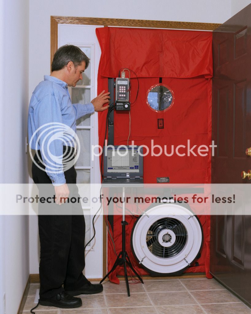
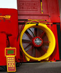
A blower door is a powerful fan that mounts into the frame of an exterior door. The fan pulls air out of the house, lowering the air pressure inside. The higher outside air pressure then flows in through all unsealed cracks and openings. The auditors may use a smoke pencil to detect air leaks. These tests determine the air infiltration rate of a building.
Blower doors consist of a frame and flexible panel that fit in a doorway, a variable-speed fan, a pressure gauge to measure the pressure differences inside and outside the home, and an airflow manometer and hoses for measuring airflow.
There are two types of blower doors: calibrated and uncalibrated. It is important that auditors use a calibrated door. This type of blower door has several gauges that measure the amount of air pulled out of the house by the fan. Uncalibrated blower doors can only locate leaks in homes. They provide no method for determining the overall tightness of a building. The calibrated blower door's data allow the auditor to quantify the amount of air leakage and the effectiveness of any air-sealing job.
Preparing for a Blower Door Test
Take the following steps to prepare your home for a blower door test:
- Close windows and open interior doors
- Turn down the thermostats on heaters and water heaters
- Cover ashes in wood stoves and fireplaces with damp newspapers
- Shut fireplace dampers, fireplace doors, and wood stove air intakes.
Importance of Building Airtightness
These are some reasons for establishing the proper building tightness:
- Reducing energy consumption due to air leakage
- Avoiding moisture condensation problems
- Avoiding uncomfortable drafts caused by cold air leaking in from the outdoors
- Making sure that the home's air quality is not too contaminated by indoor air pollution.
Duct Insulation Leakage Testing
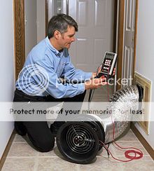
Duct leakage testing is accomplished using a duct blaster (blower). Duct leakage testing is usually performed as soon the HVAC system is installed (typically prior to framing inspection). The prerequisite for testing your duct leakage is simply that the ducts, plenum, and air handler are air tight. This usually happens as soon as the HVAC installers complete their rough-in. A smaller blower similar to the blower door is attached to a return duct and the remainder of supply and return openings are sealed to be air tight. The duct blower pressurizes the ducts and measures the amount of air leaking out of the duct and insulation system. See below for duct leakage specifications. The IECC code calls this a Duct Tightness Test.
The Details
The following is from the GA amendments to the 2009 IECC and addresses testing of the house envelope for tightness:
402.4.2.1 Testing required. Building envelope tightness and insulation installation shall be considered acceptable when tested air leakage is less than seven air changes per hour (ACH50) when tested with a blower door at a pressure of 50 Pascals (1.04 psf). The formula for calculating ACH50 and testing protocol is listed in Appendix B ‘Building Envelope and Duct Tightness Testing Protocol’. Testing shall occur after rough in and after installation of penetrations of the building envelope, including penetrations for utilities, plumbing, electrical, ventilation and combustion appliances.
The following is from the Georgia amendments to the 2009 IECC and addresses testing of HVAC ducts and insulation for tightness:
- Post-construction test: Leakage to outdoors for each system shall be less than or equal to 8 cfm (226.5 L/min) per 100 ft2 (9.29 m2) of conditioned floor area assigned to that system or a total leakage for each system with the air handler installed of less than or equal to 12 cfm (339.8 L/min) per 100 ft2 (9.29 m2) of conditioned floor area assigned to that system when tested at a pressure differential of 0.1 inches w.g. (25 Pa) across the entire system, including the manufacturer’s air handler enclosure. Conditioned floor area should be calculated using ANSI Z765, and should include all directly conditioned square footage, whether finished or not, that meets building code requirements for living space.
- Rough-in test: Total leakage for each system with the air handler installed shall be less than or equal to 6 cfm (169.9 L/min) per 100 ft2 (9.29 m2) of conditioned floor area assigned to that system when tested at a pressure differential of 0.1 inches w.g. (25 Pa) across the roughed in system. All register boots shall be taped or otherwise sealed during testing.
We also perform a duct leaking test on every new system installed.